
8/13/2019 – USED ENDER Printers back in stock! I’ve bought 3.. they help you fix ’em!
Ender 3 Pro $185.00 OBO!
Ender 3 $155.00 OBO!
Ender 5 $249.00 OBO!
CR-10 259.00 OBO!
I just completed a video on CR-10 Support Rod features and a Step-by- Step how-to guide … Check it out..
If you like what I am doing, please click like. If you are ready to start your Black Friday/Cyber Monday start here! I get a little back for my effort.
Sign up for a free month of Amazon Prime on me or if you are Student 50% off with a six month trial!
This build guide contains the out of the box upgrades I highly recommend for any CR-10.
This is my second CR-10S – the first I upgraded from a CR-10 to an S. I bought this “used” from the 3d-printer-online store on eBay. The box arrived with broken glass but 3d-printer-online quickly agreed to send me a new one. Total cost was under $300.00 with some fixin’s I had to apply.
Being used, this printer definitely had an easter egg hidden within (which we can discuss later), but I definitely benefited from someone else’s misfortune.
New on Amazon, they can be had for a little over $500.00 with free shipping.
Difficult: Easy
Price: $300ish used, $500ish new.
Time to complete: 1-3 hours (there will be some troubleshooting)
Print Area: 300x300x400mm (great size for the money.)
Features: Insulated Heated bed, Great Creality stability, Resume on power-failure, Flexible, Removable Print Surface, Ready to print!
Satisfaction: Complete!
Mandatory (IMHO) 3D Printed Upgrades
Basic Stringing Test – For Testing!
Recommended Tools
Recommended Parts/Supplies
WD-40 Specialist Dirt and Dust Resistant Dry Lube
Loctite Blue Stick, Medium Strength Thread Locker
Metric nut and screw assortment
Hatchbox PLA
Hatchbox PLA White (my favorite)
Elmer’s Purple Glue Stick
In the box.. broken glass.

Cleaned up, slightly used
Control Box and Parts box.
A view of the control Box.
Gantry Assembly.
Parts in the box laid out.
First upgrade out of the box, fix the bed leveling, in accordance with https://makersteve.com/2018/10/02/a-tale-of-two-enders-bed-level-ender-3-fix/
Unscrew all four upgraded bed leveling wheels.

Top view of the hotbed plate.
Hey look! An insulated bed.
Get your Metric nut and screw assortment out.
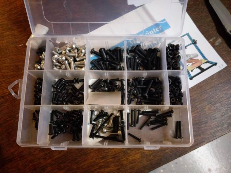
Need four each M4 nuts for the leveling fix. 
One on each screw coming through the hotbed.
All the way down and tight.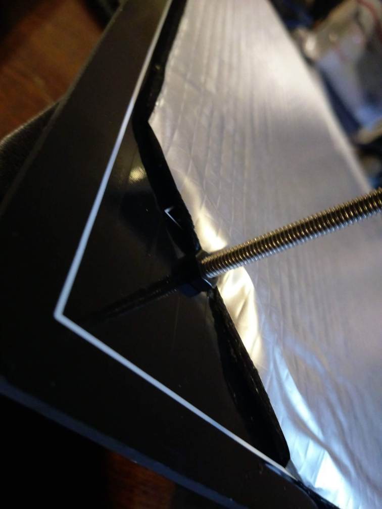
This one takes a little finesse, but it needs a nut also.

Sprint goes on before the hotbed strain relief.
Just like that.
Looks good.
Check the hotbed rollers, ensure eccentric nuts are snug but not too tight. The eccentric nuts are the 3 nuts shown, as you turn them, they tighten the rollers to the v-slot of aluminum extrusion that comprises the frame.
Make sure the bed sits flat, loosen the horizontal screws all the way around. You will probably find the bed wiggles and is not level when you push on a corner, we will fix that real quick. Stay with me.
Front and back.
Clamp one end to your work surface and tighen the opposite corner while pushing down, then tighen each corner working your way back to the clamp. Your frame should sit flat now.

This is a great opportunity to use some Loctite Blue Stick, Medium Strength Thread Locker. Just a dab on each screw.

Now put the three remaining springs back in place
Flip the hotbed over, holding the springs with all three hands and mate the hotbed back to the hotbed base.
Now place the gantry assembly on the base, it should balance.
Align the T-slot nuts as shown below so they properly seat in the v-slot of the frame. Ensure they are loosen enough for the T-slot nuts to properly engage and lock


Hold the bracket in place and snug it up, but not tight, yet.
Loctite up your screws that go in through the bottom.
Position the frame just off your table enough so you can get underneath, line up the holes and screw the base to the gantry assembly.
Like so.
Other side.
Now tighten the T-slot nuts on the bracket, left and right.

Assemble the spool holder

Connect to control box.
Break out some new filament and hang it.
Identify X-axis motor connector, X-axis endstop and Extruder.

Plug in extruder
X-axis endstop
X-axis motor
Identify the Z motor and cable(s). You will have two with a CR-10S, only one with a CR-10

Connect them to the motors.

Z-Axis motor connector and Z-axis endstop connector shown below.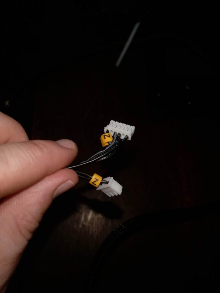
Connect the X-axis endstop
Make sure it is inserted all the way.
Connect Z-axis motor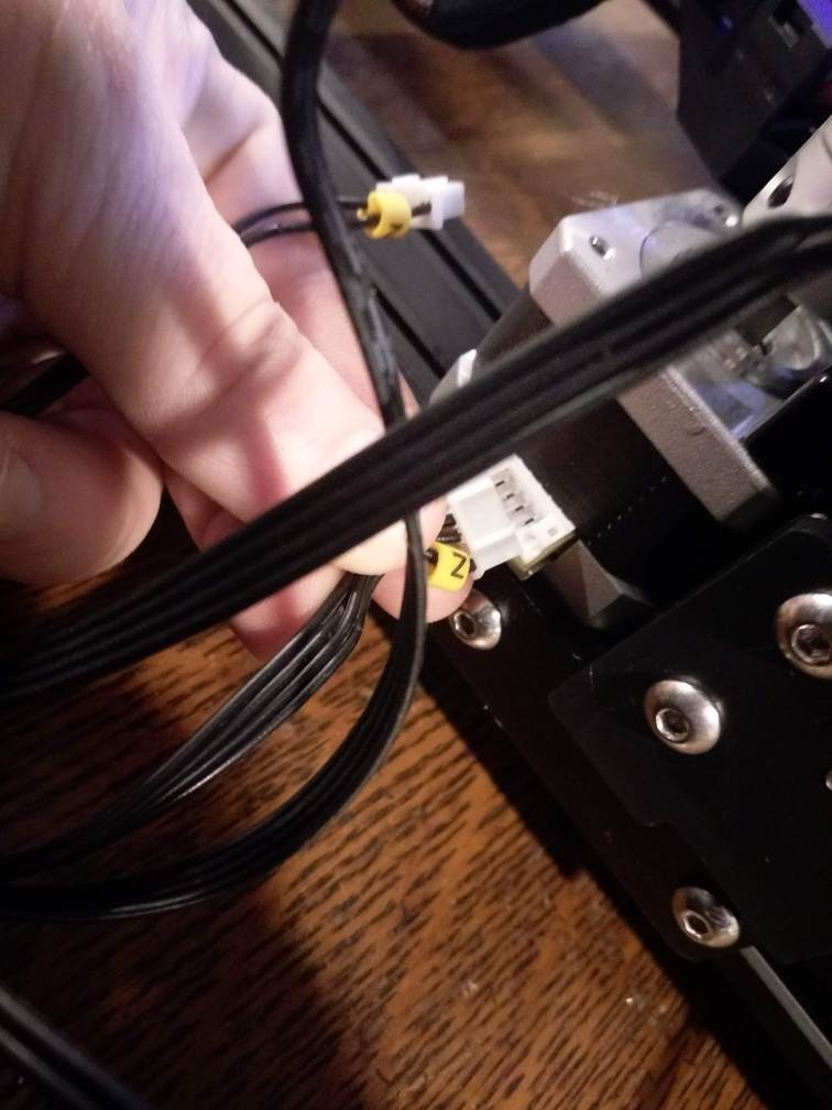
Connect Z-axis endstop
Find the two Y cables, on is for the motor, the other for the endstop.
Connect em up!
Connect the hotbed cable, it is keyed, once inserted, twist the locking ring.
Connect the hotend cable, it is keyed, once inserted, twist the locking ring.

Choose your voltage!
This is how I rock 220V in the USA!
Connect the filament sensor. If you don’t want to use it there will be a little chip that is on the end of the cable.

Tighten up and align the remaining rollers… use the eccentric nuts as shown. The rollers should not spin freely ones you are tight, do not over tighten.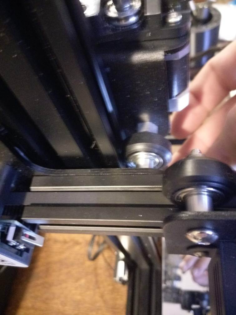
Left side…
Right side… 
Extruder assembly… they should all roll smoothly.
Let’s do some preventative maintenance on the hotend. This fix is based on The Hot End – Channel. I know this printer was used.. I know it was returned, there had to be a reason.
New printers from the factory come with gaps between the nozzle and the PFTE tubing.. I recommend fix this for brand new machines.
Loosen the hotend compression fitting

Heat up the hotend

Look at that… no good! It was leaking.
Look down the throat… 
Jam some spare PTFE tubing through.. 
Yup.. there was a booger in there!
That was reason one this printer was returned.
Get out!
New nozzle in this case to ensure no issues. If you buy replacement nozzles, ensure they are for an MK-8 Hotend! Here they are on the Creality store on eBay.
Clip that PTFE back
All the way to the scarring on the tube.
Cool it down.. 
Add some WD-40 PTFE Dry Lube

A little down the throat… 
Let it dry
Catch the drippin’s!
Good to go!
Make sure you drive the PTFE deep.. don’t stop short of the nozzle.

Put the compression fitting on.. 
Tighten it up.
Jam it in there until it stops.
If you aren’t sure, use the small wrench to press down the compression lock and push some more.
Just like that… 
Clip the extruder end.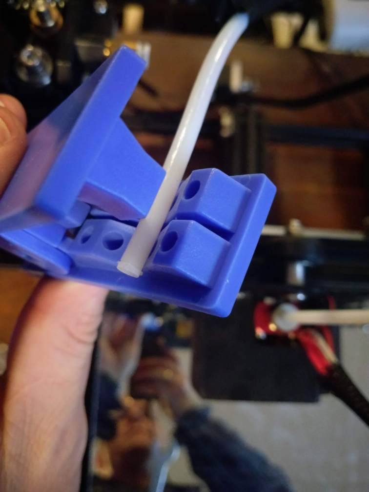
Spray some PTFE dry lube on a napkin and wipe the tube.. 
Just a bit will do.
Look how far you need the PTFE to go into the compression fitting, don’t stop short.
Break out your connector locks and clips that were listed above.
Just need one.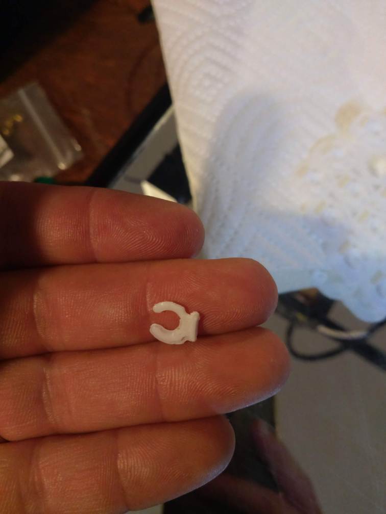
Bad-a-bing!
Cable clips, I use four.
Gorgeous.
Let’s make sure it’s level and won’t bind! See this walk-thru for more detail on leveling
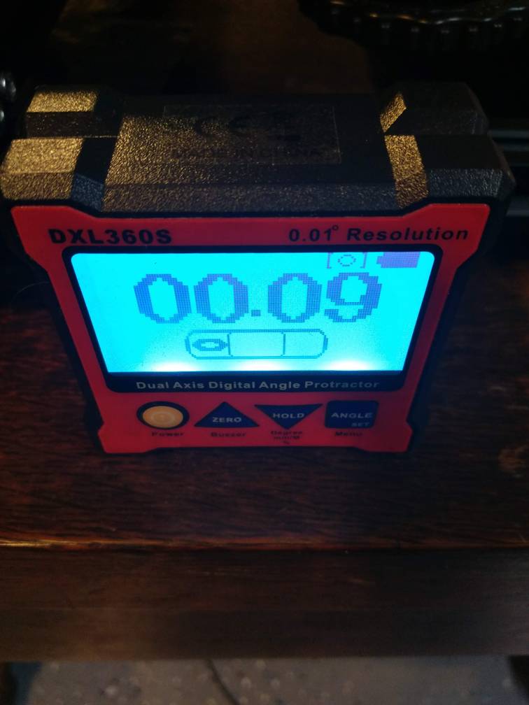
Check the surface the printer is sitting on.. yeah, I know.. OCD.
Align the gantry with the power off.. should match the upper horizontal of the frame.
Loosen the screws on that support the leadscrew.. they should just be snug, this will prevent binding.

Verify your lead screws are generally the same distance from the frame the whole way up.. left and right side.. I use three points, top, middle, bottom. Within a mm is good to go.


Grab your Lithium Grease

Put a little dabble on them lead screws.
I level the bed to the lowest point of the hotend to ensure the tip does not hit the surface.

Manually test the motors and extruder, fan and hotend..


All three axis.. 

X

Y

Z

To test the extruder, you have to heat the hotend or a safety will not allow it to move.


Test the fan.. 
Heat up the nozzle… 

Now move the extruder..

Ready to go..
I prepared a mirror to replace the broken glass as shown https://makersteve.com/2018/03/25/getting-your-print-to-stick-on-your-3d-printer/
Scratch it up!


Apply some Elmer’s Purple Glue Stick


Heat it up… feed it with filament, you are ready to go.
Not a bad first layer.. 

A little adjustment to retraction. 
Great bottom layer.
That’s it.. I will go over Aluminum Extruder and supporting rod kit installation shortly.
There is a ton of other useful stuff on Makersteve.com and more coming every week.
Be sure to check out my Ultimate Build Guide for Creality Ender 3 and the
If you find this useful, please consider purchasing products through any of the links on the page, it’s free to you and I get a little something for my time. Or, just go shopping at Amazon or Ebay or Gearbest.
You can also support me through Patreon or buy me a Ko-fi!
Happy Printing,
Steve
Hey Steve. A great and informative tutorial from beginning to end. Glad to see you got a great deal on a 10S. I have the original as well and have since opted to get the CR10S-S4 and love it as I’m expanding the herd. Looking forward to your next stuff and Great Job again.
Omg thank you so much for this I didnt know that the cr10 needs to have a eccentric nut on both sides of the uprights. Yes stupid but it’s been working all the two years I had the printer. Well bought the second and now I’m gonna put it on now that I got to see this.